


Monumental Tall Flagpole Engineering Guide
Monumental Tall Flagpole Engineering Guide
Flagpoles between 50 m and more than 100 m require project-specific structural engineering, wind assessment, foundation design and lifting coordination. They should be treated as major cantilever structures rather than as standard commercial flagpoles.
- Second-order effects should be reviewed when shaft displacement and axial load materially affect base moments.
- Wind response should include the shaft, flag, top equipment, terrain and site exposure.
- Connections, foundation details and anchor cages must follow project-specific calculations.
- Large-section lifting requires an approved lift plan, verified rigging points and qualified site supervision.
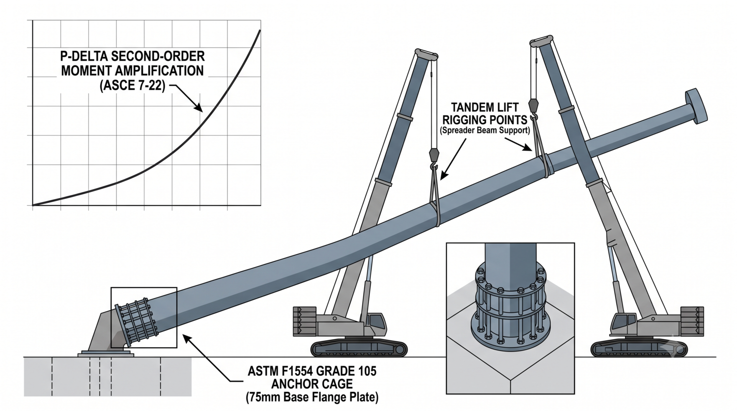
Tall flagpole projects require coordinated structural calculations, foundation design and erection planning.
1. Review Second-Order Effects
A tall flagpole carries its own weight, equipment loads, flag loads and wind loads through a slender vertical shaft. When the shaft deflects, axial loads can create additional bending moments. This is commonly referred to as the P-Delta effect.
The responsible engineer should determine whether a first-order calculation is sufficient or whether a second-order analysis is needed. The decision depends on shaft geometry, stiffness, axial load, wind exposure, boundary conditions and the applicable design standard.
2. Assess Wind and Dynamic Response
Wind design should consider the project location, terrain, exposure, height, shaft taper, flag area, top hardware and local turbulence. ASCE/SEI 7-22 may be used when required by the project documents.
Large circular shafts can experience vortex shedding and cross-wind movement. The engineer may review natural frequency, damping, stiffness, mass distribution and fatigue-sensitive details. A tapered shaft can influence the aerodynamic and structural response, but its geometry must be verified by calculation.
3. Select Shaft Sections and Connections
Very tall flagpoles may use one-piece, slip-jointed or bolted-flange construction. The appropriate solution depends on manufacturing limits, transport, lifting equipment, access, structural loads and inspection requirements.
Connections should transfer axial force, shear and bending without creating unacceptable local stresses. Internal flange connections, slip joints or other systems should be designed and detailed for the specific shaft diameter, wall thickness, bolt arrangement and erection sequence.
4. Design the Foundation and Anchor Cage
The foundation must resist overturning, shear, uplift and compression from the shaft. Depending on the soil and project conditions, the solution may involve a reinforced concrete mat, drilled foundation, pile-supported system or another engineered arrangement.
Anchor rods and cages should be coordinated with the base plate, reinforcement, concrete placement and survey controls. The final design should verify concrete strength, embedment, edge distances, corrosion protection, leveling and grout details.
5. Prepare the Heavy-Lift Plan
Long steel sections can be damaged if lifting points, sling angles or crane movements are not properly planned. The lift plan should identify section weight, center of gravity, lifting lugs, crane capacity, ground conditions, wind limits, exclusion zones and communication procedures.
Tandem lifting may be appropriate for some long sections, but it requires coordinated crane movements and qualified supervision. Spreader beams or suitable soft slings may help distribute contact pressure, subject to the approved rigging design and surface-protection requirements.
6. Control Alignment During Erection
After the base section is positioned, survey equipment can be used to check plumbness, anchor locations and flange alignment. Leveling nuts, shims or temporary supports should be used only as detailed by the engineer.
Non-shrink grout should be installed according to the approved foundation and base-plate detail. The erection sequence should define when temporary supports can be removed and when the connection is ready for final inspection.
7. Tall Flagpole Project Checklist
| Area | Information to Confirm | Review Focus |
|---|---|---|
| Structural design | Geometry, materials, axial load and wind basis | First-order or second-order analysis |
| Dynamics | Natural frequency, damping and vortex response | Movement and fatigue-sensitive details |
| Foundation | Soil data, concrete, reinforcement and anchor cage | Load transfer and constructability |
| Rigging | Weights, lifting points, cranes and wind limits | Safe erection sequence |
| Inspection | Welds, bolts, alignment, grout and coating | Release for final operation |
Frequently Asked Questions
When is P-Delta analysis required for a tall flagpole?
The responsible engineer should assess the effect when axial load and lateral displacement can materially increase bending moments or affect serviceability. The requirement depends on the project calculation basis.
Is a one-piece shaft always suitable for a 100 m flagpole?
No. Transport, lifting, manufacturing, access and site restrictions may require a multi-section design with engineered joints.
Can two cranes be used to erect a long flagpole section?
They can be used when the lift is designed and supervised as a tandem operation. Crane capacity, load sharing, rigging points, communication and weather limits must be confirmed.
What foundation is suitable for a monumental flagpole?
The foundation depends on wind loads, soil conditions, groundwater, shaft geometry and the building or site constraints. It must be designed by the responsible civil and structural engineers.
References
- ASCE/SEI 7-22 Design Loads
- NAAMM FP 1001 Guide Specifications for Design of Metal Flagpoles
- AISC Structural Steel Resources
- Fortune Pole
For tall flagpole engineering documents, structural coordination and erection planning, contact Fortune Pole.