


Synchronized Stadium Flag Hoisting Guide
Synchronized Stadium Flag Hoisting Guide
Stadium flag hoisting systems must coordinate mechanical movement, electrical control, safety functions and event operations. A suitable design should consider travel distance, lifting speed, encoder feedback, emergency stopping, maintenance access and integration with the venue control system.
- Define the required flag travel, timing sequence and operating conditions before selecting the winch.
- PLC and VFD control can support coordinated acceleration, deceleration and speed adjustment.
- Encoder feedback can help detect position differences between multiple hoists.
- Brakes, emergency stops and manual recovery should be reviewed as part of the complete safety system.
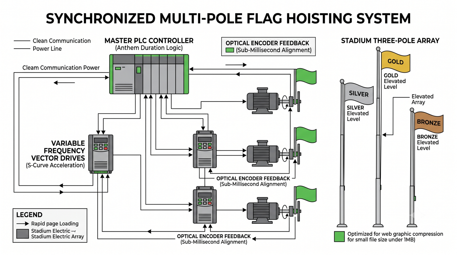
A stadium hoisting system should coordinate motion control, feedback, safety and event operation requirements.
1. Define the Hoisting Sequence
Start with the event sequence rather than the motor specification. Confirm the number of flagpoles, starting and stopping positions, flag travel distance, required completion time and acceptable movement tolerance.
When several flags travel different distances, each hoist may require a different speed profile. The control system should be configured from verified project data instead of relying on a single fixed motor speed.
2. Use PLC and VFD Control Appropriately
A Programmable Logic Controller can coordinate commands, interlocks, timing signals and fault responses. Variable Frequency Drives can adjust motor frequency and support smoother acceleration and deceleration than a simple direct-on-line starter.
The final speed profile depends on the motor, gearbox, drum, cable, flag weight, travel distance and venue requirements. S-curve or ramped movement may be considered where reducing sudden tension changes is important.
3. Add Position Feedback
Rotary encoders or other position sensors can provide feedback from each hoist. The PLC can compare the feedback from multiple drives and identify a difference caused by cable movement, slipping, sensor faults or uneven loading.
Feedback does not remove the need for mechanical inspection. The system should define calibration procedures, allowable deviation, fault handling and a safe stop response.
4. Design Braking and Emergency Recovery
Flag systems operating above event areas require a documented safety concept. The design may include spring-applied brakes, emergency stop circuits, overspeed monitoring, limit switches and controlled restart procedures.
A manual recovery method may be useful when electrical power or the control network is unavailable. Its operation should be tested, protected against unintended release and included in the venue’s maintenance procedures.
5. Coordinate the Flagpole and Internal Equipment
Internal cables, counterweights, drums and sensors need sufficient clearance and access. Shaft joints, internal ledges and service doors should be reviewed to prevent interference with moving components.
A one-piece shaft may reduce field joints, but transport, lifting, access and installation conditions may make a sectional shaft more suitable. The choice should be based on the complete project rather than a single fabrication preference.
6. Integrate With Stadium Controls
Event systems may exchange commands and status information with audio-visual or building-management systems through protocols such as Modbus TCP/IP, BACnet/IP or DMX512. Compatibility must be checked with the venue integrator before equipment is purchased.
Important integration points include start permission, sequence selection, emergency stop, fault status, manual mode, position status and maintenance lockout. Audio timing should be tested using the actual event control workflow.
7. Stadium System Specification Checklist
| Area | Information to Confirm | Review Focus |
|---|---|---|
| Motion | Travel distance, timing and speed profile | Smooth and repeatable operation |
| Control | PLC, VFD, sensors and interlocks | Commands, feedback and fault response |
| Safety | Brakes, limits, emergency stop and recovery | Safe stop and restart conditions |
| Integration | Protocol, I/O points and control authority | Venue system compatibility |
| Maintenance | Access, calibration, inspection and spare parts | Long-term serviceability |
Frequently Asked Questions
Can multiple flagpoles be synchronized automatically?
They can be coordinated when the hoists, sensors, controllers and mechanical loads are designed as one system. The allowable position difference and fault response should be defined in the project requirements.
Why use a VFD instead of a simple motor starter?
A VFD can support adjustable speed and ramped acceleration or deceleration. Whether it is required depends on the motor, load, timing and control sequence.
Are encoder sensors enough to guarantee safe operation?
No. Encoder feedback supports position monitoring but does not replace brakes, limit switches, emergency stops, mechanical inspection or operator procedures.
Can a stadium flag system connect directly to the audio system?
It may connect through a suitable control interface, but protocol compatibility, signal ownership, emergency priority and testing must be confirmed with the venue integrator.
References
- IEEE Power and Control Resources
- NAAMM FP 1001 Guide Specifications for Design of Metal Flagpoles
- ASCE/SEI 7-22 Design Loads
- Fortune Pole Stadium Flagpole Control Systems
For stadium flagpole layouts, control schematics and project coordination, contact Fortune Pole.