


Smart City Flagpole Integration Guide
Smart City Flagpole Integration Guide
Smart city flagpoles should be designed as coordinated structural and electrical systems rather than ordinary decorative poles with equipment added later. The project team must define the equipment payload, wind exposure, cable routes, enclosure requirements, grounding, thermal conditions, access and maintenance responsibilities before finalizing the pole design.
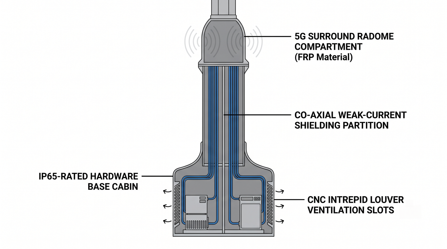
Smart city flagpole integration reference for structural, electrical and maintenance planning.
1. What Changes When Electronics Are Added?
A traditional flagpole is mainly reviewed for its own weight, wind exposure, flag loading, foundation connection and operating hardware. A multifunctional smart pole adds new design variables, including equipment weight, mounting height, projected area, cable pathways, heat generation, access panels and electrical protection.
Typical equipment may include cameras, environmental sensors, lighting controllers, public-address devices, wireless access equipment or small-cell hardware. The exact equipment list should be confirmed by the owner, telecom contractor and electrical engineer. Equipment names alone are not enough for structural design because each device may have different weight, dimensions, wind area, power demand and maintenance requirements.
2. Structural Design: Payload, Wind and Eccentricity
Equipment mounted near the top of a pole can create concentrated dead load and an eccentric bending effect. The design review should consider the weight of each device, the mounting bracket, cable protection, maintenance platform or access hardware, and any future equipment allowance specified by the owner.
Wind design should include the pole, flags, brackets, equipment housings and other exposed accessories. A compact enclosure can still increase the projected area at the top of the structure. The final design should therefore be based on the local wind criteria, exposure, importance category, load combinations, foundation conditions and equipment arrangement.
ASCE/SEI 7-22 may be used as a reference for general design loads where it is adopted by the project or local code. It does not automatically approve a particular flagpole configuration. A licensed structural engineer should verify the shaft, base plate, anchor bolts and foundation reactions for the actual site.
3. One-Piece and Sectional Shaft Options
A one-piece or single-section shaft may reduce field joints and simplify the visual profile when transport, lifting and site access allow it. It is not automatically required for smart city applications. Sectional construction may be more practical where road transport, crane capacity or installation access limits the shaft length.
The selection should be based on the complete project scope, including equipment location, mounting details, delivery route, lifting plan, joint design, inspection access, replacement strategy and maintenance requirements. The shaft configuration should follow the engineering calculations rather than a marketing label.
4. Electrical Separation and EMC Review
Smart city poles may contain power cables, control wiring, data cables, fiber-optic lines and grounding conductors. The project electrical engineer should define cable separation, conduit routes, access points, protection devices and testing requirements.
A metal shaft can affect radio-frequency propagation, cable routing and equipment performance. A device mounted inside a metal enclosure may require a radio-transparent housing, external antenna arrangement or a manufacturer-approved radome. These details depend on the equipment frequency range, antenna design, enclosure material and local telecommunications requirements.
Do not describe an internal partition as a universal “co-axial shielding chamber” unless that exact configuration has been engineered and tested for the project. In many cases, properly separated conduits, cable glands, grounding and equipment-specific EMC controls may be more appropriate.
5. Thermal Management and Weather Protection
Outdoor electronics must be evaluated for solar radiation, ambient temperature, humidity, dust, rain, condensation and service access. An enclosure rating such as IP65 may be specified for a particular compartment, but the rating must be verified for the complete enclosure, door, cable entries, seals and installed equipment.
Passive ventilation, heat sinks, filtered vents or active cooling may be considered after the equipment heat output and environmental conditions are known. A chimney effect should not be assumed to provide sufficient cooling without a thermal calculation or equipment manufacturer data.
6. Smart City Flagpole Specification Matrix
| Design area | Information to define | Documents to request |
|---|---|---|
| Structural payload | Equipment weight, mounting height, bracket geometry and projected wind area | Structural calculations, equipment schedule and mounting drawings |
| Electrical and data systems | Power demand, cable types, conduits, grounding and separation requirements | Single-line diagram, cable schedule and electrical protection plan |
| Weather and thermal conditions | Temperature range, solar exposure, moisture, dust and equipment heat output | Enclosure data, thermal review and equipment environmental specifications |
| Operations and maintenance | Access method, replacement route, inspection frequency and service ownership | Maintenance plan, access details and installation responsibilities |
7. Procurement Checklist
- Confirm the complete equipment list before structural calculations.
- Record device weight, dimensions, mounting height, wind area and power demand.
- Define the local wind, seismic, foundation and electrical code requirements.
- Confirm whether wireless devices require a radome or radio-transparent enclosure.
- Separate power, control, data, fiber and grounding routes according to the electrical design.
- Review access panels, locks, replacement paths and maintenance equipment.
- Request material information, finish data, drawings, inspection records and installation assumptions from the supplier.
Frequently Asked Questions
Can any commercial flagpole be converted into a 5G smart pole?
No. The shaft, foundation, equipment brackets, cable routes, grounding and thermal conditions must be reviewed for the specific equipment and site.
Does a one-piece shaft guarantee better performance?
No. It may reduce field joints, but the final result also depends on material, wall thickness, geometry, connections, foundation, equipment loads, wind criteria and installation quality.
Is IP65 automatically suitable for smart pole electronics?
No. The required enclosure protection depends on the equipment, environment and project specification. The complete enclosure and cable-entry system should be verified.
What should be sent to a flagpole manufacturer?
Send the pole height, flag dimensions, site wind criteria, equipment list, payload weights, mounting positions, cable requirements, finish, foundation interface, delivery route and installation scope.
References
- ASCE/SEI 7-22 Minimum Design Loads and Associated Criteria
- NAAMM FP 1001 Guide Specifications for Design of Metal Flagpoles
- IEEE Electromagnetic Compatibility Standards Collection
- Fortune Pole Flagpole Manufacturer
- Fortune Pole Flagpoles and Flagpole Components
- Fortune Pole Factory and Manufacturing Facilities