


Seismic Design Criteria for Commercial Flagpoles
Seismic Design Criteria for Commercial Flagpoles
Commercial flagpoles installed in earthquake-prone regions should be designed as site-specific cantilever structures. The review must consider local ground motion, soil conditions, pole geometry, flag loading, equipment loads, base connections, anchor bolts and foundation behavior. A standard wind-rated flagpole should not be assumed to satisfy seismic requirements without an engineering review.
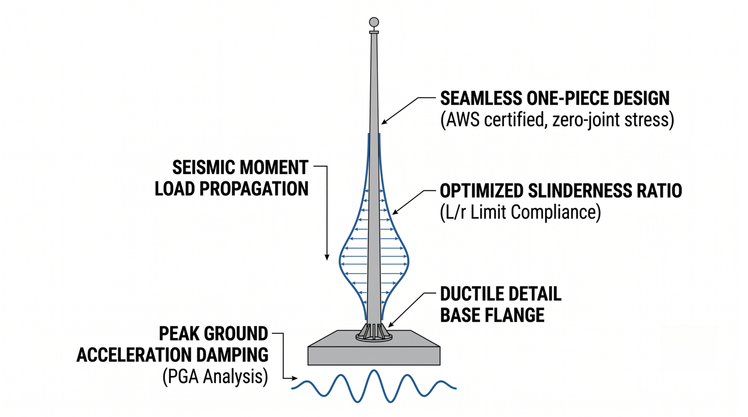
Commercial flagpole seismic design reference for structural and procurement review.
1. Why Seismic Design Is Different From Wind Design
Wind primarily applies pressure to the exposed surface of the pole and flags. Seismic movement begins at the ground and creates inertial forces through the mass of the structure and attached components. The pole, flag hardware, brackets, finials and foundation connection may therefore respond differently during an earthquake than during steady wind loading.
Projects in active seismic regions should be reviewed by the owner, structural engineer, geotechnical consultant and relevant authority. The project team should confirm the seismic design category or equivalent local classification, site soil conditions, expected ground motion, importance of the installation and required performance objectives.
2. Ground Motion and Cantilever Response
A flagpole behaves as a slender cantilever fixed at its base. Ground movement creates lateral acceleration, while the mass distributed along the shaft produces inertial forces. The response depends on pole height, mass distribution, stiffness, damping, connections and foundation flexibility.
Peak ground acceleration is only one part of the seismic design process. Engineers may also need design response spectra, site coefficients, load combinations, structural periods, soil classification and local code provisions. These values should come from the adopted code, approved hazard data and project-specific engineering documents.
ASCE/SEI 7-22 can be used where adopted by the project or local jurisdiction. It provides general provisions for design loads and load combinations, including seismic and wind effects. It does not provide an automatic approval for a particular flagpole product.
3. Slenderness, Taper and Ductility
The slenderness ratio compares effective length with the radius of gyration of a structural section. Excessive slenderness can increase sensitivity to buckling and lateral displacement. However, reducing slenderness by simply making the pole heavier is not always the correct solution because increased stiffness and mass can change the seismic force demand.
A balanced tapered geometry may provide a more efficient distribution of material along the shaft. The base region generally requires careful review because it transfers the largest combined effects from bending, shear, axial force and connection reactions. Wall thickness, diameter, alloy, weld details and transition geometry should be selected through calculation rather than a fixed generic table.
Ductility means that selected components can undergo controlled deformation before ultimate failure when permitted by the design method. The required ductility level, detailing and acceptance criteria must be determined by the project engineer and applicable code.
4. One-Piece and Sectional Flagpole Configurations
A one-piece or single-section shaft may reduce the number of field joints and provide a continuous visual profile. It still requires a suitable transport route, lifting plan, crane capacity and site access. It is not automatically mandatory for seismic regions.
Sectional poles may be practical where transport or installation conditions limit the shaft length. The joint configuration, field welding, slip connections, inspection access and replacement strategy should be included in the seismic review. The correct choice depends on the complete structural system, not only on whether the shaft is one piece.
5. Base Plates, Anchor Bolts and Foundations
The base connection is one of the most important parts of a seismic flagpole system. The review should include the base plate, anchor bolts, grout, concrete pedestal, reinforcement, embedment, edge distances, overturning resistance and possible concrete failure modes.
ASTM F1554 may be relevant when the project specifies steel anchor bolts of the grades covered by that standard. The selected anchor material, installation method, nuts, washers, corrosion protection and inspection requirements must match the structural design and contract documents.
Foundation sizing cannot be finalized from pole height alone. A geotechnical report may be needed to confirm soil strength, stiffness, liquefaction risk, groundwater, slope conditions and settlement behavior.
6. Seismic Flagpole Specification Matrix
| Review area | Information to define | Documents to request |
|---|---|---|
| Seismic hazard | Local hazard parameters, adopted code and seismic classification | Code basis, hazard data and engineering criteria |
| Site and soil | Site class, soil strength, groundwater and geotechnical risks | Geotechnical report and foundation recommendations |
| Pole geometry | Height, taper, diameter, wall thickness, material and flag loading | Structural calculations and general arrangement drawings |
| Base connection | Base plate, anchors, concrete pedestal and reinforcement | Base details, anchor schedule and foundation design |
7. Procurement Checklist
- Confirm the project location and adopted seismic design requirements.
- Obtain geotechnical information before finalizing the foundation.
- Define pole height, flag size, material, taper, wall thickness and equipment loads.
- Review the complete base connection, anchor bolt and concrete design.
- Confirm whether the project permits one-piece or sectional transportation and lifting.
- Request material certificates, welding information, inspection records and finish data.
- Define installation, inspection, maintenance and post-event assessment responsibilities.
Frequently Asked Questions
Can a wind-rated flagpole be used in an earthquake zone?
Not automatically. Wind design and seismic design use different load mechanisms. The project engineer must review the local hazard, site conditions, pole geometry, connection and foundation.
Does a one-piece flagpole eliminate seismic risk?
No. It may reduce field joints, but seismic performance also depends on material, geometry, base connection, anchor bolts, concrete, soil and installation quality.
Are ASTM F1554 Grade 55 anchor bolts mandatory for every seismic project?
No. The required anchor type and grade depend on the adopted code, project calculations, authority requirements and structural design.
What should a supplier receive before preparing a quotation?
Provide the site location, seismic criteria, soil information, pole height, flag dimensions, material preference, equipment loads, foundation interface, finish and installation scope.
References
- ASCE/SEI 7-22 Minimum Design Loads and Associated Criteria
- NAAMM FP 1001 Guide Specifications for Design of Metal Flagpoles
- ASTM F1554 Standard Specification for Anchor Bolts
- Fortune Pole Flagpole Manufacturer
- Fortune Pole Flagpoles and Flagpole Components
- Fortune Pole Factory and Manufacturing Facilities