


Outrigger Flagpole Engineering Guide
Outrigger Flagpole Engineering Guide
Wall-mounted and outrigger flagpoles transfer wind, dead load and operational forces into a building facade. Their design should coordinate anchor capacity, cantilever stiffness, facade waterproofing, installation access and long-term maintenance.
- Review the wall substrate, anchor group and load path before selecting the bracket.
- Check cantilever deflection under wind and dead load using project-specific calculations.
- Coordinate drip edges, flashing and sealants with the building-envelope system.
- Joints, winches, access doors and auxiliary supports require the same attention as the shaft.
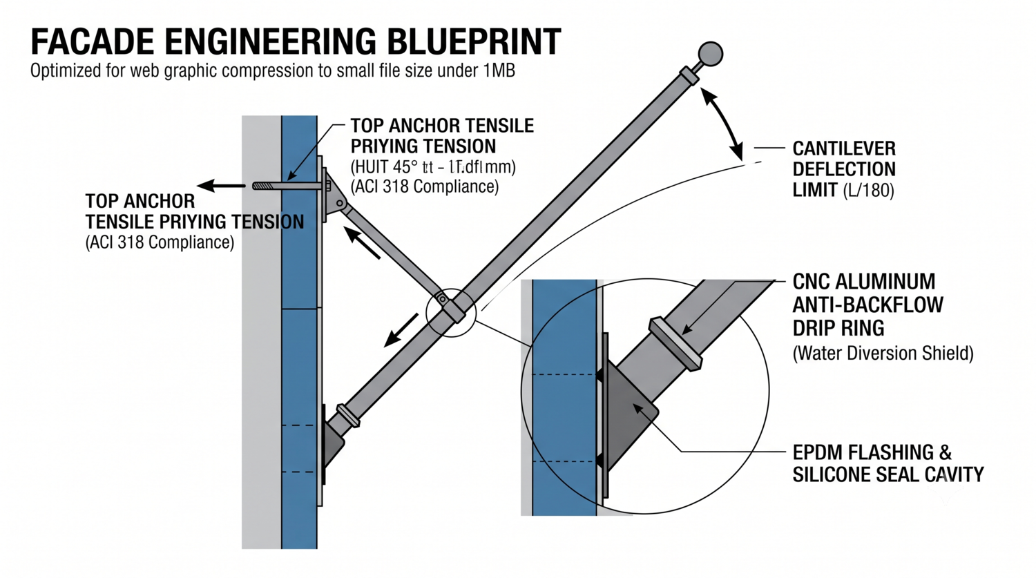
Outrigger flagpole design should connect structural calculations with facade waterproofing and access planning.
1. Review the Facade Load Path
An outrigger flagpole acts as an eccentric cantilever attached to a wall or structural frame. Wind on the shaft and flag creates shear, bending and tensile forces in the mounting bracket and anchor group.
The engineer should identify the actual wall substrate, reinforcement, steel framing, masonry condition, edge distances and load path. A bracket designed for solid reinforced concrete may not be suitable for hollow block, thin cladding or an unverified facade support.
2. Check Anchor Tension and Prying
Moment loading can place tension on the upper anchors and compression on the lower bearing area. Bracket plate flexibility may increase local anchor demand, so the connection should be checked for tension, shear, prying, concrete breakout, pull-out, splitting and edge failure.
ACI 318 anchoring provisions may be applicable when the connection is made to concrete. Anchor type, embedment, spacing, installation method and inspection requirements should follow the approved structural design.
3. Control Cantilever Deflection
Deflection depends on load, projection length, material stiffness and the area moment of inertia. A basic elastic relationship for a uniform cantilever is:
Tip deflection = Force × Length³ ÷ (3 × Modulus of Elasticity × Moment of Inertia)
The project engineer should define the serviceability limit for the shaft and bracket. The limit may depend on appearance, flag movement, equipment clearance, facade tolerances and connection durability.
4. Protect the Building Envelope
Rainwater can run along an inclined shaft toward the wall bracket. Without a suitable detail, water may reach cladding joints, insulation, masonry or wall penetrations.
Possible protection measures include drip edges, collars, flashing, sealant joints and drainage paths. The final detail must be compatible with the facade material and should be reviewed by the building-envelope contractor. No universal drip-ring size or sealant arrangement should be assumed.
5. Select the Shaft and Mounting Configuration
Vertical wall mounts, inclined outriggers and horizontal projections have different load and access conditions. The shaft material, wall thickness, bracket geometry and anchor layout should be selected together.
A one-piece shaft may reduce field joints, but transport, lifting, fabrication length and site access may favor a sectional design. Any joint must maintain alignment, transfer design forces and remain accessible for inspection.
6. Coordinate Winches and Internal Components
Internal winches, cables and access doors can be useful for angled or elevated flagpoles. The internal equipment frame should provide adequate clearance, drainage, support and safe access for operation.
External halyards may move against the facade in wind, but an internal system is not automatically required for every project. The choice depends on height, angle, access, flag size, maintenance procedures and operating requirements.
7. Consider Auxiliary Supports for Long Projections
Long horizontal projections may require an additional diagonal strut, tie rod or secondary bracket. The support changes the load path and should be designed for tension, compression, connection forces and movement compatibility.
Auxiliary supports should not be added only to reduce visible deflection. Their wall connection, corrosion protection, access and architectural appearance must also be coordinated.
8. Outrigger Flagpole Checklist
| Area | Information to Confirm | Review Focus |
|---|---|---|
| Substrate | Concrete, steel, masonry, reinforcement and edge distances | Verified load path |
| Anchors | Type, embedment, spacing and installation method | Tension, shear and breakout |
| Deflection | Projection, loads, material and section stiffness | Serviceability and alignment |
| Waterproofing | Drip edge, flashing, sealant and drainage | Facade-envelope continuity |
| Operation | Winch, cable, access and maintenance | Safe serviceability |
Frequently Asked Questions
Can a standard vertical wall bracket be used for an inclined outrigger?
Not automatically. The inclination changes the force directions and may increase tension and prying in the upper anchors. The bracket and anchor group require a project-specific review.
Which anchor type is suitable for a wall-mounted flagpole?
It depends on the substrate and access. Chemical anchors, cast-in rods, through-bolts or a steel backing plate may be appropriate after structural review.
Does every angled flagpole need a drip ring?
Not necessarily, but rainwater control must be addressed. The suitable detail depends on the shaft angle, facade, bracket and waterproofing system.
Can a long horizontal outrigger use an auxiliary strut?
Yes, when the strut and its wall connections are designed for the revised load path. It should be coordinated with architecture, drainage and maintenance access.
References
- ASCE/SEI 7-22 Design Loads
- ACI 318 Structural Concrete Resources
- NAAMM FP 1001 Guide Specifications for Design of Metal Flagpoles
- Fortune Pole
For CAD bracket details, anchor calculations and facade coordination, contact Fortune Pole.