


Motorized Flagpole Servo Control: Drive Selection and Feedback
Short answer: a motorized flagpole does not automatically need a high-end servo system. The right drive depends on flag size, pole height, duty cycle, wind exposure, synchronization accuracy, safety requirements and maintenance access. Closed-loop control is most valuable when the system must stop accurately, coordinate multiple poles, detect faults and recover position after interruptions.
Key engineering points
- Servo, PMSM and VFD-driven induction motors can all be valid choices when matched to the real load and operating cycle.
- Closed-loop feedback improves speed and position control, but a motor-shaft encoder alone cannot prove true flag height if the cable slips or stretches.
- Brake, limit switch, overload and emergency stop design matter more than peak motor torque on paper.
- Regenerative energy during lowering should be reviewed when the load can back-drive the motor.
- Remote drives, long encoder cables and VFD outputs require EMC, shielding, grounding and manufacturer-approved cable lengths.
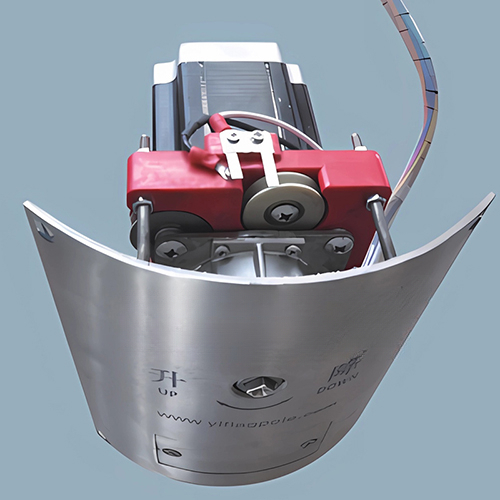
What a motorized flagpole drive must do
A motorized flagpole drive is a vertical lifting system. It must raise and lower the flag smoothly, stop at repeatable positions, resist wind-related load variation and hold the load safely when motion stops. In a single pole, the main objective may be reliable everyday operation. In a stadium or civic plaza with many poles, the objective often expands to synchronized motion and central monitoring.
The drive package normally includes a motor, gearbox or drum, brake, cable or belt path, upper and lower limit devices, local controls, electrical protection and a control cabinet. Higher-end systems may add an encoder, torque monitoring, network status points, event presets and alarm logging.
The specification should start with the operating requirement rather than the motor label. Required travel speed, maximum flag size, expected wind range, number of cycles per day, allowed noise level, position tolerance and emergency procedure should be written before selecting the drive.
Motor selection: induction, PMSM or servo?
A basic AC induction motor can be suitable for simple applications, especially where the system uses contactor control, clear end limits and a modest duty cycle. Adding a variable frequency drive can improve acceleration, deceleration and speed adjustment.
A permanent magnet synchronous motor, often used in servo packages, can provide high torque density and efficient low-speed control. It may be useful when the drive must fit into a compact pole cavity or when synchronized operation requires accurate speed and position response. That benefit comes with more demanding electronics, feedback wiring, tuning and service knowledge.
There is no automatic rule that PMSM is always better. For some projects, a rugged geared motor with well-designed limits and a reliable brake is the better lifecycle choice. For others, a servo or closed-loop vector drive justifies its cost through smoother movement, better diagnostics and multi-pole coordination.
Closed-loop feedback and position accuracy
Closed-loop control means the controller measures what the drive is doing and corrects the command. In a typical servo system, the current loop regulates torque, the velocity loop regulates speed and the position loop regulates target movement. The exact loop rates and performance depend on the drive, motor, encoder and tuning.
Encoders can be incremental or absolute. An incremental encoder may require a homing routine after power loss unless the controller has another way to recover position. An absolute encoder can report its position after power returns, but it still reports the position of the shaft where it is installed.
This distinction matters. If the encoder is mounted on the motor shaft, it confirms motor rotation. It does not directly measure flag height after the drum if the cable stretches, slips, winds unevenly or is re-terminated. For true height control, the design may need load-side feedback, a drum encoder, redundant limit references, cable-tension monitoring or a periodic calibration cycle.
Wind load, torque and regenerative energy
Flag loads vary sharply with wind, wet fabric, flag size and halyard friction. The drive should be sized for starting torque, steady lifting torque, acceleration, stopping and holding. A motor that can lift the flag in calm air may still trip on overload when wind adds drag or when the cable path is contaminated.
During lowering, the load may back-drive the motor. In that case the drive can generate energy back into its DC bus. Some systems only need controlled braking inside the drive rating; others need a braking resistor or regenerative unit. The design should state the lowering speed, expected load range and how overvoltage faults are prevented.
Mechanical holding is separate from motion control. A brake should be selected for static holding, emergency stopping where applicable, duty cycle, environmental exposure and maintenance inspection. Software torque control should not be the only method keeping a suspended flag or counterweight in position.
Limits, brakes and fault handling
A safe motorized flagpole needs independent end-of-travel protection. Software position limits are useful, but hardwired upper and lower limit devices or safety-rated limit logic may still be required. Overtravel protection should stop the drive before the winch damages the cable, top assembly or access door.
Useful fault inputs include brake release feedback, motor overload, encoder fault, upper limit, lower limit, access-door interlock, emergency stop, cable slack and drive fault. Not every project needs every input, but each omitted point should be a deliberate decision.
If the system is part of a larger stadium control network, define what happens after a fault. The controller should record the fault, stop in a defined state and require an approved reset method. Automatic restart after a power interruption should be avoided unless the risk assessment explicitly allows it.
Control cabinet, wiring and EMC
Drive location affects reliability. A drive mounted inside the pole may simplify motor cabling but expose electronics to temperature swings, condensation and service constraints. A remote drive cabinet may improve access and cooling, but it introduces longer motor and encoder cable runs.
No fixed remote distance is safe for every system. Cable length depends on the drive manufacturer, motor insulation, encoder type, feedback voltage, shielding, grounding and switching frequency. Long VFD motor leads can create reflected voltage and electromagnetic interference. Encoder and sensor cables should be routed separately from motor power cables and terminated according to the manufacturer's instructions.
IEC 61800-3:2022 addresses electromagnetic compatibility requirements for adjustable speed power drive systems. It is a useful reference when motor drives, long cables and low-voltage feedback are present in the same installation.
Standards and safety references
IEC 60204-1:2016+A1:2021 applies to electrical, electronic and programmable electronic equipment and systems for machines within its scope. It can inform control-cabinet design, protective bonding, marking, stop functions and maintenance access for motorized flagpole machinery.
IEC 61800-5-2:2016 covers functional safety requirements for safety-related power drive systems. If the design relies on drive-integrated functions such as safe torque off or safe stop, the selected drive and wiring must be validated for the required safety function.
IEC 60034-1:2026 covers rating and performance for rotating electrical machines. Efficiency-class documents such as IEC 60034-30-1 apply to defined motor categories, but they should not be used casually to claim that every compact servo motor meets a certain IE class.
Drive specification matrix
| Design item | Basic motorized pole | Closed-loop servo package | What to verify |
|---|---|---|---|
| Motor and gearbox | Geared AC motor or DC drive | Servo or PMSM drive with tuned control loops | Torque, speed, duty cycle, heat rise and serviceability |
| Feedback | Upper and lower limits | Encoder plus independent limit references | Whether feedback measures motor rotation or true load position |
| Holding method | Gearbox friction or simple brake | Rated holding brake with feedback where required | Static load, wind, wear, inspection interval and failure mode |
| Regeneration | Often unmanaged in small systems | Braking resistor or regenerative path when needed | Lowering load, wind back-drive and DC bus overvoltage margin |
| Commissioning | Limit setup and functional test | Loop tuning, homing, fault tests and synchronization checks | Test script, acceptance tolerance and maintenance procedure |
What should be included in the drive submittal?
- Maximum flag size, travel speed, pole height, number of daily cycles and design wind limit for operation.
- Motor, gearbox, drum, brake and cable data sheets.
- Torque calculation for lifting, lowering, acceleration, holding and wind-related drag.
- Encoder or feedback type, mounting location, resolution and homing method.
- Upper limit, lower limit, overtravel, slack-cable and emergency stop logic.
- Drive cabinet location, enclosure rating, cooling method and service access.
- Motor, brake, encoder and sensor cable lengths with shielding and grounding details.
- Commissioning test plan covering travel limits, position repeatability, faults and manual recovery.
For system-level coordination, see Fortune's stadium flagpole control-system guide and commercial flagpole component guide.
Frequently asked questions
Is a servo motor required for every motorized flagpole?
No. A servo is useful when the project needs accurate position control, synchronized motion, diagnostics or smooth low-speed behavior. Simpler poles may work well with a geared motor, limits and a reliable brake.
Does an absolute encoder eliminate cable slippage?
Not by itself. If the encoder is on the motor shaft, it measures motor rotation. Cable stretch, drum slip or uneven winding may still cause height error unless the system uses load-side feedback, references or calibration.
Can the drive be installed away from the pole?
Yes, but the distance must follow the drive and encoder manufacturer's limits. Long motor and feedback cables require proper shielding, grounding, separation and EMC review.
What happens if power fails while the flag is moving?
The safe response depends on the design. The system may brake and hold, stop and require manual recovery, or continue on backup power. The required behavior should be written into the sequence of operation.
Engineering notice
This guide explains drive-selection and feedback-control considerations. Final motor sizing, braking, wiring, safety functions and commissioning tests should be prepared or reviewed by qualified electrical and automation professionals using project-specific load data.
References
- IEC 60034-1:2026, Rotating electrical machines - Rating and performance
- IEC 60204-1:2016+A1:2021, Electrical equipment of machines
- IEC 61800-3:2022, EMC requirements for adjustable speed power drive systems
- IEC 61800-5-2:2016, Functional safety requirements for power drive systems
- ANSI/NAAMM FP 1001-07, Guide Specifications for Design of Metal Flagpoles