


Water-Tight Flagpole Drainage Guide
Water-Tight Flagpole Drainage Guide
Architectural flagpoles are hollow structures that may be exposed to wind-driven rain, humidity, condensation and temperature changes. Moisture management should therefore be addressed through the top assembly, shaft joints, access doors, base details, material compatibility and maintenance plan.
1. Identify How Moisture Enters the Shaft
Moisture may enter through revolving truck interfaces, halyard openings, access doors, sectional joints, damaged coatings or installation details. A closed shaft is not automatically a completely dry shaft because air inside the column can also contain moisture.
Wind-driven rain can move through small gaps when wind pressure and rainfall act together. The exact exposure depends on the local climate, the height of the flagpole, the truck design, the access-door geometry and the quality of installation.
2. Understand Internal Condensation
Daily temperature changes can cause the internal air and metal wall to pass through different dew-point conditions. When the inner surface becomes cooler than the air inside the shaft, condensation may form and move downward.
Condensation risk should be considered together with humidity, ventilation, shaft volume, surface temperature, coatings and the location of the base plate. The design objective is to avoid long-term standing water in concealed areas, not to claim that condensation can never occur.
3. Control Water at the Top Assembly
The top revolving truck, bearings, halyard entry and ornament connections should be reviewed as a weather-exposed assembly. Where a sealed truck is specified, confirm the seal material, bearing arrangement, drainage path, service requirements and compatibility with the expected temperature and UV exposure.
Seals reduce water entry but require correct compression, alignment and maintenance. A weather-resistant top assembly should be supported by product drawings and installation instructions rather than a general water-tightness statement.
4. Provide Controlled Base Drainage
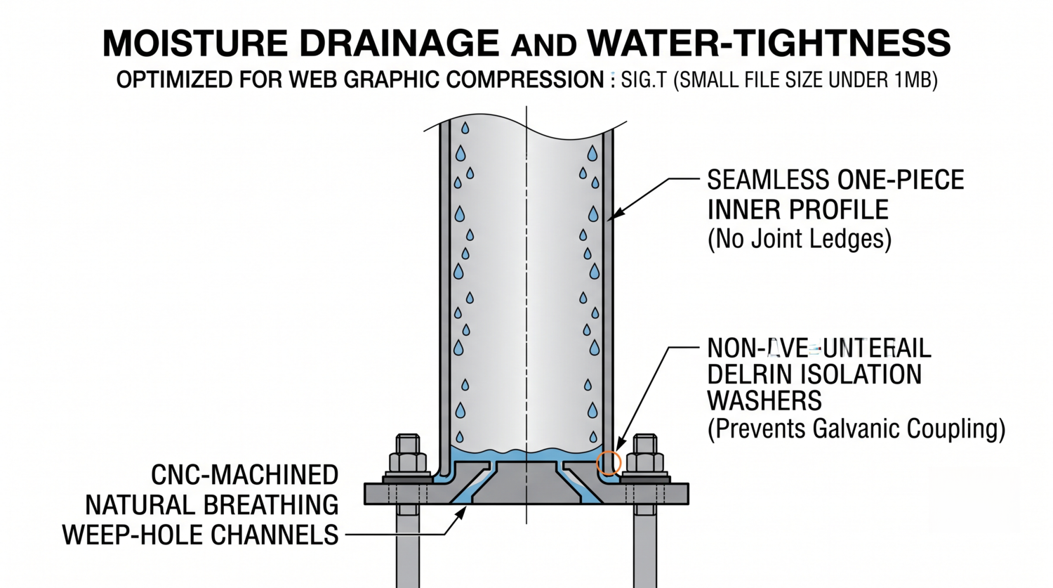
A base detail may include weep holes or other drainage paths at the lowest practical internal point. The opening size, location, slope, protection and relationship to the foundation must be coordinated with the structural design.
Drainage openings should not weaken the base plate, interfere with anchors, allow excessive debris entry or become blocked by grout. During installation, any temporary protection used to keep drainage paths open must be approved by the responsible engineer and removed or completed according to the installation procedure.
5. Reduce Crevice and Galvanic Corrosion
Standing moisture in narrow gaps can create a localized corrosion environment. The risk is influenced by the material grade, surface condition, chloride exposure, joint geometry, drainage and inspection access.
When aluminum is connected to steel anchors or other dissimilar metals, the project should review electrical isolation, washers, sleeves, coatings, fasteners and drainage. Non-conductive isolators may be appropriate, but the selected material must be compatible with the load, temperature, moisture and installation conditions.
6. One-Piece and Sectional Shaft Design
A one-piece shaft can reduce some internal ledges and field joints, but transportation and lifting requirements may require a sectional construction. Sectional flagpoles can be suitable when joint sleeves, tolerances, seals, drainage and inspection are properly engineered.
Field welding should follow approved procedures and inspection requirements. Factory fabrication can improve repeatability, but it does not remove the need to verify the actual installed condition.
7. Materials and Surface Protection
Material selection should consider the site, alloy or steel grade, corrosion environment, coating, weld zones and expected maintenance. For aluminum architectural surfaces, the project may specify an applicable anodizing or coating performance standard such as AAMA 2605.
For stainless steel, review grade, finish, weld cleaning, passivation and contact with dissimilar metals. For coated steel, specify surface preparation, primer, coating thickness, adhesion and repair procedures.
8. Moisture Management Specification Matrix
| Design area | Specification focus | Evidence to request |
|---|---|---|
| Top assembly | Weather-resistant truck, seals and service access | Product drawings and maintenance instructions |
| Shaft interior | Condensation, joints and internal surface condition | Section details and inspection plan |
| Base drainage | Weep holes, screens, slope and grout coordination | Base drawings and installation method |
| Dissimilar metals | Isolation, coatings, fasteners and drainage | Material compatibility review |
| Maintenance | Inspection, cleaning and replacement access | Service schedule |
9. Procurement Checklist
- Define local rainfall, humidity, temperature and corrosion exposure.
- Review truck, halyard entry, access-door and joint details.
- Confirm whether controlled base drainage is required.
- Coordinate drainage openings with the base plate, anchors and grout.
- Review aluminum-to-steel isolation and fastener compatibility.
- Specify coating, anodizing, passivation and repair requirements.
- Provide structural calculations for wind, shaft and foundation.
- Include inspection and maintenance instructions in the handover package.
Frequently Asked Questions
Does a closed flagpole shaft remain completely dry?
Not necessarily. Wind-driven rain, installation gaps and internal condensation can introduce moisture. The design should provide appropriate sealing, inspection and controlled drainage.
Are weep holes suitable for every flagpole?
Not automatically. Their size, location and protection must be coordinated with the shaft, base plate, anchors, grout, structural design and local environment.
Why is isolation important between aluminum and steel?
Moisture can create an electrical path between dissimilar metals and increase galvanic corrosion. Isolation components may reduce this risk when correctly selected and installed.
Can one-piece forming eliminate all moisture risks?
No. It may reduce some joints and internal ledges, but top assemblies, access doors, drainage, coatings and maintenance still require project-specific review.
References
- NAAMM FP 1001: Guide Specifications for Design of Metal Flagpoles
- ASCE/SEI 7-22: Minimum Design Loads
- ASTM standards and technical information
- Fortune Pole commercial flagpole solutions
For a project-specific quotation, provide the location, height, flag dimensions, rainfall and wind exposure, material, finish, truck design, base drainage, foundation details and maintenance requirements.