


Commercial Flagpole Specification Guide
Commercial Flagpole Specification Guide
A commercial or monumental flagpole should be specified as part of the building and site design, not as an isolated catalog item. The specification should connect wind criteria, foundation design, material selection, finishes, access equipment, BIM coordination, quality records and tender documentation.
- Use the governing building code and project-specific wind criteria.
- Select shaft materials and finishes according to height, exposure and maintenance needs.
- Coordinate the base plate, anchor cage, foundation, lighting and underground services.
- Request traceable material, welding, coating and dimensional records.
- Use BIM or CAD data only after the approved geometry and interfaces are confirmed.
1. Establish the Design Basis
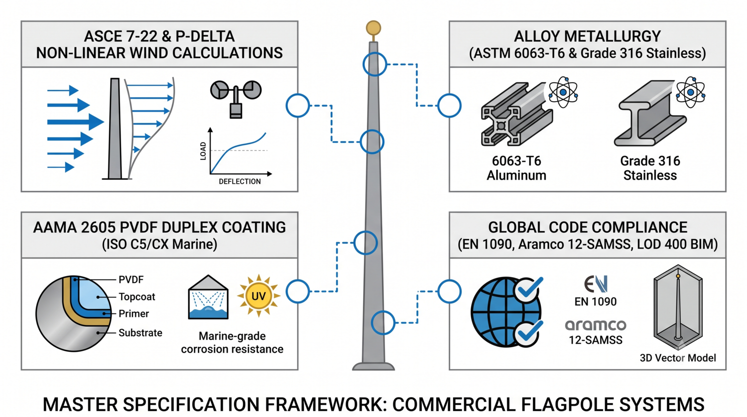
The first step is to define the project location, flagpole height, flag area, exposure category, importance level, surrounding terrain and operating conditions. For projects in North America, ASCE 7-22 may be part of the design basis. Other regions may require Eurocodes, local standards or owner-specific criteria.
The structural engineer should confirm the applicable wind speed, exposure, topographic effects, gust response, flag loading assumptions, serviceability limits and foundation requirements. Standard catalog charts can support early budgeting, but they should not replace site-specific calculations.
2. Coordinate the Foundation and Base Connection
The foundation, anchor cage, base plate and shaft must be treated as one load-transfer system. The submittal should show anchor diameter, bolt spacing, embedment, projection, leveling method, grout, drainage and finished paving levels.
For tall or monumental flagpoles, the design may also require review of second-order effects, dynamic response, soil conditions and construction tolerances. The applicable engineer should approve the foundation and anchor details before concrete placement.
3. Select Materials for the Environment
Material selection depends on exposure, appearance, structural requirements, transportation and maintenance. Architectural aluminum can be suitable for many commercial applications, while stainless steel or coated structural steel may be selected for higher loads, coastal exposure or specific architectural requirements.
Material documentation should identify alloy or steel grade, temper or strength condition, thickness, surface preparation and applicable standards. Avoid using broad terms such as “marine grade” or “heavy duty” without stating the actual material and performance requirements.
4. Specify Fabrication and Weld Quality
The specification should clearly state whether the shaft is one-piece, sectional, sleeved or assembled on site. A factory-assembled system can reduce field operations, but transport limits, crane access, shaft length, lifting points and site safety still need to be reviewed.
Weld documentation should identify the welding procedure, welder qualifications, visual inspection and any non-destructive testing required by the project. The inspection level should match the structural importance and governing code rather than relying on an unsupported percentage or guarantee.
5. Match the Finish to the Exposure
Architectural finishes should be selected for the actual environment. Common options include brushed stainless steel, anodized aluminum, powder coating, PVDF coating and multi-layer corrosion-protection systems.
The finish schedule should identify color, gloss, preparation, coating system, inspection method, repair procedure and maintenance requirements. For coastal, desert or industrial locations, the project team should define the expected corrosivity and cleaning program before choosing the finish.
6. Coordinate Optional Equipment
Commercial and monumental projects may include internal or external halyards, manual winches, electric hoists, rotating trucks, lighting, flag spreaders, access doors or automated event controls.
Each option affects the shaft, base, power supply, maintenance access and operating procedure. Electrical equipment should be reviewed for voltage, enclosure rating, grounding, emergency operation and local electrical requirements. Automated systems should not be specified without confirming control interfaces and maintenance responsibilities.
7. BIM, CAD and Digital Coordination
BIM and CAD data can help coordinate anchor cages, base plates, rebar, conduits, paving, facade elements and access clearances. The model should use approved dimensions and clearly identify type parameters, instance parameters, materials, finishes and maintenance zones.
Clash detection is useful before construction, but a model does not replace structural calculations, approved shop drawings or field verification. Revision status should be controlled across the architectural, structural, electrical and supplier models.
8. Tender and Quality Documentation
| Document group | Information to include | Review purpose |
|---|---|---|
| Structural | Loads, shaft dimensions, base plate and anchor details | Confirm design intent and load transfer |
| Materials | Grades, thicknesses, certificates and traceability | Confirm specified materials |
| Fabrication | Welding procedures, inspection and dimensional records | Verify production quality |
| Finish | Coating system, color, preparation and maintenance | Match appearance and exposure |
| Digital data | Approved CAD, Revit or coordination files | Reduce interface conflicts |
9. Documents to Request Before Award
- Site-specific structural calculations or design criteria.
- General arrangement and foundation connection drawings.
- Material, coating and corrosion-protection data.
- Welding, inspection and dimensional quality records.
- Installation method statement and lifting requirements.
- Operation, inspection, maintenance and spare-parts information.
- Revision-controlled CAD or BIM files where digital coordination is required.
Frequently Asked Questions
Is ASCE 7-22 suitable for every commercial flagpole project?
No. ASCE 7-22 may apply to projects in the United States, but the governing code depends on the project location, owner requirements and authority having jurisdiction.
Is a one-piece flagpole always better than a sectional system?
Not always. A one-piece system may reduce field assembly, while a sectional system may be more practical when transport, site access or lifting limits apply.
What finish is best for a coastal location?
There is no universal answer. The finish should be selected according to the actual corrosivity, material compatibility, appearance, cleaning program and project budget.
Can BIM data replace structural calculations?
No. BIM supports coordination and information exchange. Structural calculations, approved drawings and field verification remain separate project requirements.
References
- NAAMM FP 1001 Guide Specifications for Design of Metal Flagpoles
- ASCE/SEI 7-22
- AAMA Aluminum Specifications
- AWS Structural Welding Publications
For commercial flagpole engineering, BIM coordination and tender documentation, visit Fortune Pole.