


BIM and Revit Flagpole Modeling Guide
BIM and Revit Flagpole Modeling Guide
BIM and Revit models can help coordinate flagpoles with foundations, facades, electrical services and maintenance requirements. The model level should follow the project BIM execution plan and should be supported by approved engineering and fabrication documents.
- Use the required LOD for the actual design, coordination or fabrication stage.
- Model anchor cages, base plates, brackets and service clearances when they affect coordination.
- Use clash detection to identify conflicts before concrete, cladding or services are installed.
- Keep BIM parameters consistent with approved drawings, calculations and product data.
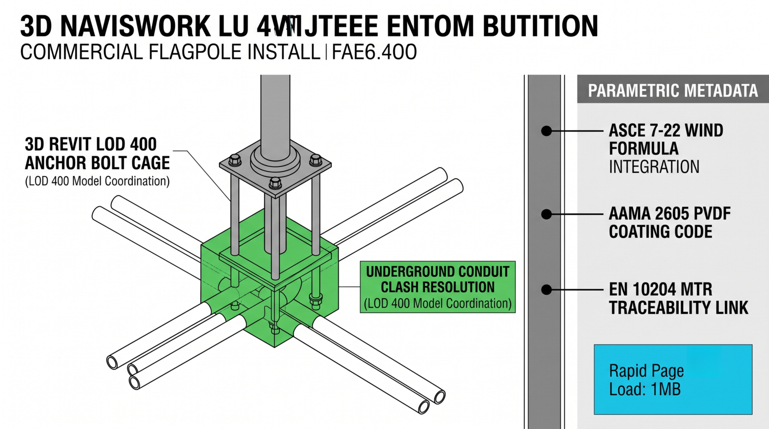
A coordinated flagpole model can connect structural, architectural, electrical and maintenance information.
1. Define the Required LOD
LOD should describe the reliability and intended use of the model, not only its visual detail. Early models may show approximate location and size, while later models may include verified dimensions, interfaces and fabrication information.
The required LOD should be stated in the BIM execution plan. A model should not contain engineering information that has not been verified or approved for the project stage.
2. Coordinate Foundations and Facades
Ground-mounted flagpoles may interface with foundation pads, anchor cages, reinforcement, conduits, drainage and paving. Wall-mounted or outrigger flagpoles may interface with curtain-wall mullions, structural steel, cladding brackets and weather seals.
A detailed model can help the project team review clearances and identify potential conflicts. The model should be coordinated with structural drawings and verified site dimensions before construction.
3. Use Revit Families and Parameters Carefully
A Revit family can contain geometry, connection points, material information, access zones and selected engineering data. Type parameters can describe properties shared by a product family, while instance parameters can describe a specific location or installation.
Parameters should have clear names, units and data sources. Wind values, material grades, coating systems and anchor information should link to approved documentation rather than being copied from an unverified generic family.
4. Run Clash Detection Before Installation
Coordination software such as Navisworks can be used to review conflicts between the flagpole, reinforcement, anchor bolts, electrical sleeves, drainage pipes, facade frames and nearby equipment.
Clash detection results should be grouped by discipline, location, severity and responsible party. Each issue should be assigned a status and resolved through an updated model or approved design change.
5. Coordinate Specification and Procurement Data
Digital models can carry information about material, finish, dimensions, electrical requirements, access, maintenance and approval status. This can help architects, contractors and facility managers use a consistent product description.
BIM data should not be used to hide unverified performance claims. Product data, calculations, material certificates and coating records should remain available as separate project documents.
6. Connect BIM With Fabrication
Approved geometry may support CAD/CAM preparation, CNC forming, laser cutting and shop drawing production. Before export, the model must be checked for units, coordinates, tolerances, revision status and fabrication suitability.
Digital transfer can reduce re-entry errors, but it does not replace shop drawing review, dimensional inspection, welding inspection or final approval. The fabrication file should be controlled by revision.
7. Plan COBie and Handover Data
When required by the project, COBie or another asset-data format can carry equipment identification, manufacturer information, maintenance intervals, spare parts and warranty records.
The handover data should reflect the installed product. Any changes made during fabrication or installation should be incorporated into the final record model where required by the contract.
8. BIM Flagpole Checklist
| Area | Information to Confirm | Review Focus |
|---|---|---|
| LOD | Required stage, detail and information reliability | BIM execution plan |
| Geometry | Shaft, base plate, brackets and access zones | Dimensions and interfaces |
| Clashes | Rebar, anchors, conduits, drainage and facade frames | Location and resolution status |
| Parameters | Materials, finishes, loads and maintenance data | Approved source documents |
| Handover | Installed product, revisions and asset records | As-built information |
Frequently Asked Questions
Is LOD 400 required for every flagpole project?
No. The required level depends on the BIM execution plan, project complexity, coordination needs and fabrication requirements.
Can a Revit family replace structural calculations?
No. A model can organize and display engineering information, but structural calculations and approvals remain separate professional documents.
What should be included in a flagpole BIM family?
Depending on the stage, it may include geometry, connection interfaces, access clearances, materials, finishes, equipment zones and approved project data.
Can a BIM model be sent directly to CNC equipment?
It may support CAD/CAM preparation after review, but units, coordinates, tolerances, revisions and fabrication drawings must be checked before production.
References
- BIMForum Level of Development Specification
- ASCE/SEI 7-22 Design Loads
- NAAMM FP 1001 Guide Specifications for Design of Metal Flagpoles
- Fortune Pole
For Revit families, BIM coordination and fabrication documentation, contact Fortune Pole.